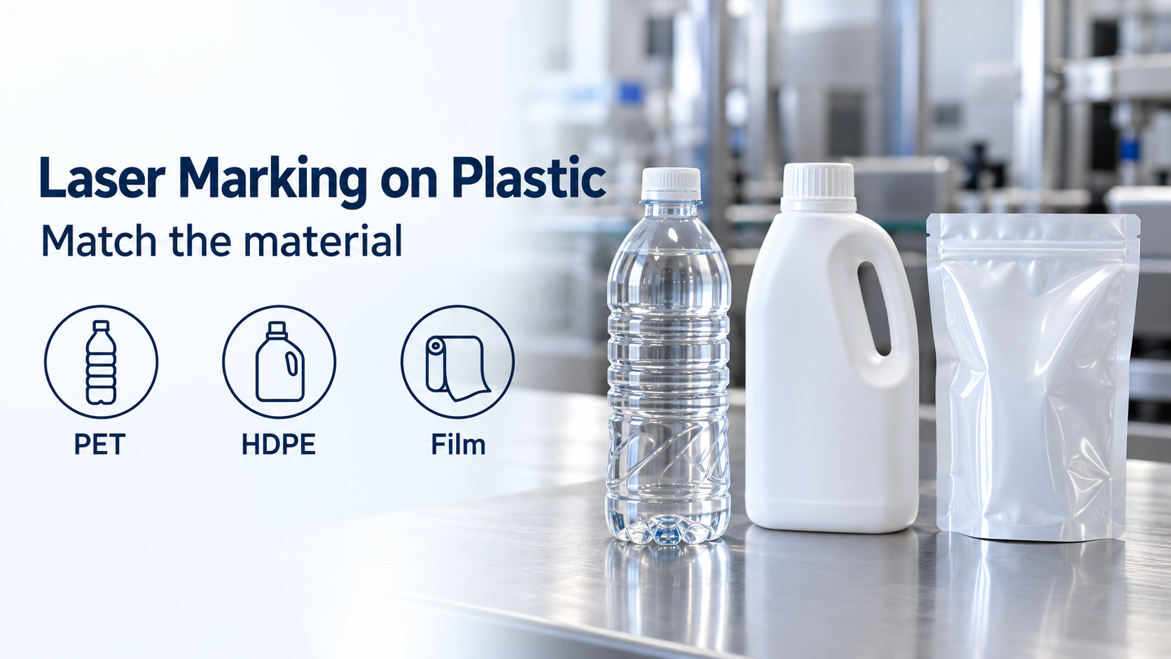
A readable code that damages a bottle wall or a film barrier turns laser marking on plastic packaging into product loss. For PET, HDPE and laminated film, choose among CO2, fiber and 355 nm UV by the documented response of the exact packaging construction, then confirm package integrity and available marking time.
The direct answer: begin thin-wall PET evaluation with the documented CO2 foaming option; include UV when assessing white HDPE; and keep all three laser families conditional for laminated film until the outer marking layer and underlying barrier have been evaluated. Fiber belongs on the shortlist where the actual formulation produces the required mark. A polymer name or an attractive sample code cannot establish that a different bottle, color or laminate will behave the same way. The comparison below identifies supported starting points and the evidence needed to release a production specification.
Quick specs: distinguish wavelengths from package approvals
Use the wavelength and material references as starting conditions, not settings to copy into a laser controller. The OEM documents below were accessed on 19 October 2026; page numbers refer to the physical PDF pages.
| Input or item | Typical value or source | Why it matters |
|---|---|---|
| Thin-wall PET response | 9.3 µm CO2 foaming, contrasted with 10.6 µm CO2 deeper engraving; Videojet CO2 guide, p. 10 | A readable surface effect and material removal have different consequences for the wall |
| White HDPE candidate | 355 nm UV, Videojet 7920 brochure, source specification p. 8 and application p. 5 | Evidence is for a named application, not every HDPE formulation |
| Fiber on plastics | Color change or engraving varies with the plastic; Videojet fiber guide, p. 6 | The actual material response must justify selection |
| Laminated film marking zone | UV-sensitive outer film or white knockout zone; Videojet flexible-film infographic, p. 1 | The outer marking layer and the protective construction are separate qualification questions |
| Wall, layer and marking depth | Not specified for the reader’s package | No safe depth or universal minimum thickness can be assigned |
The Videojet CO2 sample guide provides the PET comparison. Its separate recommendation for laminated paperboard does not establish a wavelength for a laminated film pouch.
Compare CO2, fiber and UV by the failure they must prevent
The useful comparison is package-specific: retain a candidate only when its mark mechanism fits the material and the package still meets its acceptance criteria. These are evidence boundaries, rather than a ranking of laser families.
| Material | CO2 starting point | Fiber starting point | UV starting point | Dominant Failure Mode & Prevention |
|---|---|---|---|---|
| PET bottle | The CO2 guide documents foaming for thin walls and engraving for thicker PET | The retrieved fiber guide does not establish a PET-bottle approval | Require evidence for the exact PET bottle; short wavelength alone is insufficient | Local wall weakening or burn-through: distinguish surface foaming from engraving, then assess the marked bottle against its package requirements |
| HDPE container | No general HDPE operating window established by the retrieved CO2 guide | General plastics evidence does not qualify a particular HDPE color or formulation | The 7920 brochure explicitly identifies white HDPE | Unacceptable contrast or surface damage: retain the exact resin, color and additive specification in the trial record |
| Laminated film | The CO2 guide describes coating removal, reactive coatings and thin-film burn-through risk | The flexible-film document includes fiber as conditional on film type | The film document describes color change in a suitable outer layer or knockout zone | Damage to the protective construction: evaluate the actual laminate and marking location, alongside code quality |
For PET, the CO2 guide, p. 10 explains why its foaming option differs from deeper engraving. It supplies no minimum wall thickness for an unknown bottle. Reducing power without assessing the resulting mark and wall is not a substitute for choosing the appropriate interaction.
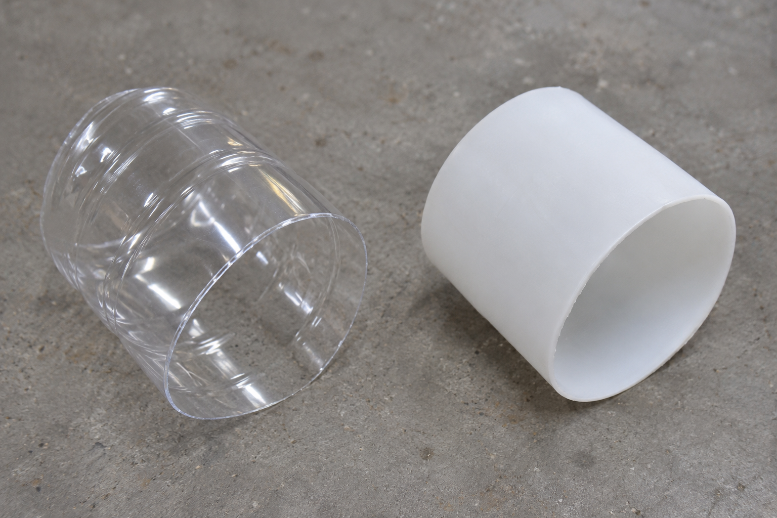
The cut edges show that wall pieces are separate objects. They are not measured thicknesses, mark depths or qualified samples.
For HDPE, the 7920 brochure, pp. 5 and 8 supports a white-HDPE application and the specified UV wavelength. Changing pigment or material formulation creates a new evaluation question. The Coherent UV solution brief explains photochemical color change and illustrates HDPE packaging, but neither document supplies operating settings for every HDPE container.
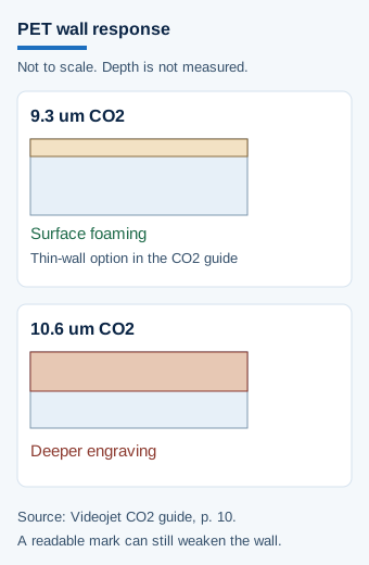
Schematic, not to scale. The contrast follows the CO2 guide, page 10. Neither panel is a measured depth or a bottle-wall specification.
Treat a laminate as a construction, not a single plastic
Qualify the actual laminate and intended code location before accepting any laser family. Videojet’s flexible-film infographic states that CO2, fiber and UV can mark flexible packaging depending on film type. It describes UV color change in an outer layer containing a UV-sensitive material, such as titanium dioxide, or in a white knockout zone, and calls for testing to ensure continued package protection.
Record the converter’s construction reference, receiving face, printed or reactive layer, marking location and relevant barrier requirements. Keep unknown layer thicknesses unknown. A demonstration on a sealing area does not establish suitability on the body of a pouch, and a dark code does not establish barrier retention.
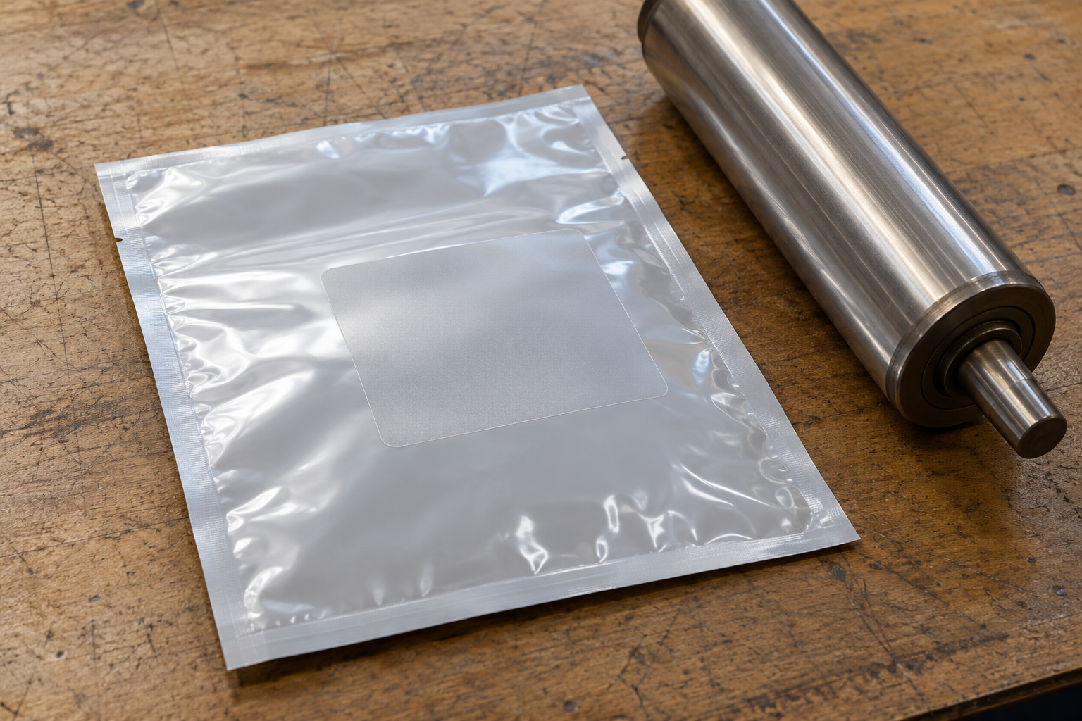
Illustrative film sample and a downstream contact surface. The patch is not a code, and the photograph does not show layer count, barrier retention or a passed package test.
The fiber sample guide, p. 6 describes different thermal marking responses across plastics. That supports material-specific evaluation; it does not justify transferring an illustrated result to an undocumented laminate. Use the substrate evaluation guide to organise material identity, receiving face and downstream-contact records when comparing a laser candidate with an ink-based alternative.
Apply a marking-time threshold before accepting line capacity
For a station marking packs sequentially, the complete marking cycle must fit inside the available pack interval. Longer messages, repositioning and the actual moving marking window belong in that assessment.
Threshold rule: if the required marking cycle exceeds the available interval at the target rate, reject that configuration for sequential operation until the message, station arrangement or production rate changes. A short demonstration code cannot settle this check for the production message.
For rate R in packs/min, the ideal sequential time budget is:
t_available [s/pack] = 60 [s/min] ÷ R [packs/min]
Illustrative planning example, 19 October 2026: assuming 300 packs/min through a single sequential marking position gives 60 ÷ 300 = 0.20 s/pack, before allowing for the usable marking window and cycle overhead. This is arithmetic under stated assumptions, not an OEM throughput rating.
Obtain the full-message marking time for the actual package path and retained material. Neither the bottle geometry nor the available scan field can be inferred from the resin name.
Set the cost boundary at accepted packages
Ink-free marking removes an ink or ribbon purchase, but the economic comparison must include the work required to keep the station producing acceptable packages. The 7920 brochure also discusses beam shielding and fume extraction; those are part of the installation and maintenance scope.
| Cost boundary | Record for the comparison |
|---|---|
| Consumables and maintenance | Displaced ink or ribbon, extraction service materials, optics care and planned service |
| Changeover and restart | Time to load the correct message, restore focus and accept the first package |
| Rejected output | Packaging and any packed product lost because of weak codes or damaged material |
| Unbuffered stoppages | Lost line time when the coding station cannot release acceptable packs |
The consumable saving is insufficient when added maintenance, downtime and reject costs exceed it over the same operating period. Compare the candidates within the packaging coding equipment guide using the same message, material revision and accepted-output boundary. No fixed payback follows from removing the ink supply.
Method and sources
This comparison uses retrieved OEM documents to distinguish supported material responses from unqualified applications. Source access was 19 October 2026. The time-budget example is an explicitly assumed calculation; package geometry, marking settings and measured performance remain specific to the production application.
- Videojet, CO2 Laser Coding and Marking Sample Guide: pp. 8 and 10, film response and PET marking effects.
- Videojet, 7920 brochure: pp. 3, 5 and 8, protection, white HDPE and source specification.
- Videojet, flexible-film infographic: p. 1, film-dependent selection and qualification, copyright 2024.
- Videojet, fiber sample guide: p. 6, different plastic responses.
- Coherent, UV plastics solution brief: p. 1, photochemical mechanism and HDPE illustration, June 2020.
Updated October 2026.